I have a problem with buying motors for mass manufacture; it’s a problem of trust. Take, for example, the Solarbotics GM3; every motor manufacturer in China has a copy of this motor collecting dust in their catalog. Each and every one of them claims that their motor is stronger, faster, etc. I need to decide if I want to order thousands of these motors and I have no easy way to check their performance.
I’ve observed that this motor has played a form of the telephone game for mechanical engineering. A great example of this is the compliant clutch. The original version of this motor has a little two part clutch in it that can flex out of the way when the load is exceeded. Most of the Chinese copies of this motor still have a two part gear, they’ve just disabled the clutch entirely. My best guess is that at some point a manufacturer made a quick tooling change for a customer to disable the clutch. Then another manufacturer got one to copy, and copied the change without understanding its purpose.

Anyway, I started looking around online for a way to measure the motor’s output. It’s a small motor, but I figured someone has solved this problem. Nothing exactly right. So I got to looking a bit more and discovered a measurement tool called a Prony Brake. This seemed interesting, but I couldn’t imagine a practical way to get it to work on such small motors. Then I stumbled across a variation called the rope brake dynamometer. This, I felt, was something I could work with.

Dynamometer
In a normal rope brake dynamometer you’ve got a rope around a wheel. On one end you have a weight and on the other a spring scale. As the motor changes speed you can see the force on the spring scale increase or decrease depending on which side of the rotation you have it on. Then it’s a formula away from having the power curve.
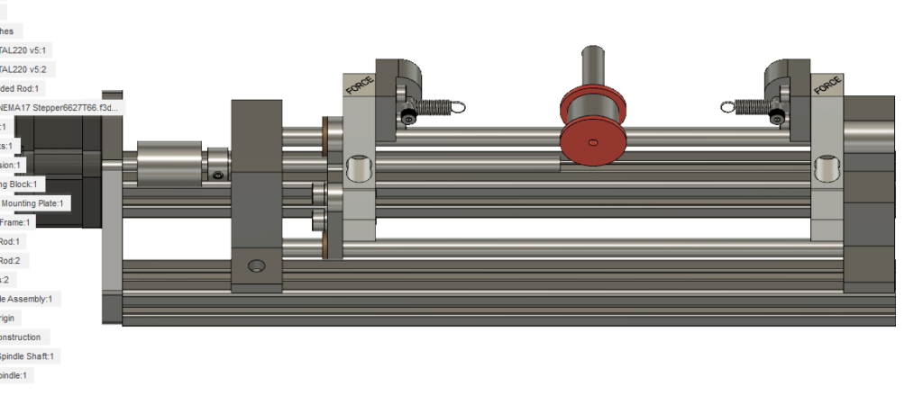
I wanted a way to increase the “mass” of the weight so I could stall the motor and see the full torque curve. I also wanted to be able to arbitrarily set the mass depending on the motor, to do this I came up with this configuration:
My plan is to wrap a small thread around a known spindle size. On each end of the thread I’ll have an extension spring. As I expand the springs, I’ll measure the force at each end. Then it’s a matter of subtracting the readings to get my torque. After that it’s only an angular velocity measurement away from getting the power output of the motor.

To measure the force produced I settled on some of these generic load cells from Sparkfun. I thought about ordering cheaper ones from eBay or Amazon, but I figure that if one is designing measuring equipment you might as well start with something that has a little QC behind it. They also sell a breakout board for an interesting chip called HX711. This takes all the headache out of interpreting the output from the load cell and should generally make things a bit more repeatable.
On top of that I’ve got a teensy on order, some stepper drivers in a box somewhere, and a motor driver likewise. Hopefully I can cobble together the electronics and most of the mechanics from 3D printer discards.
With the electronics worked out I started to design the perfect mechanical assembly. It would be a nice precision construction; made out of metal. It would move beautifully, mechanical engineers would admire it for years. It would cost hundreds—- wait, maybe I should check if this whole idea actually works first.
So I paused that design and forced myself to make a really crap version out of plastic first. Rather than being able to support any arbitrary motor, this one would be designed for exactly one motor. All I need is something to test. Which is where I am today.

So my next steps are simple in concept. I’ve ordered all the electronics. I’ve started my 3D print. I’ll assemble it all, wire it up, write some code, and see if it works. If I can generate some curves I’ll move on to some fancier design work.
My eventual goal is an open source design that can measure just about any small motor.
Next time on Part 2: Does it work?
Any update on how it worked? This is a really interesting project. I expect to be doing something similar, but with smaller load cells, to get the motor parameters for a motor needed for a bot. I’m thinking of using some nylon string wrapped around the spindle.